Basicly to get a functional speedo meter out of your palm we need these
two components.
PabiloII comunicates using the Palm serial port with the speedo interface.
Speedo sends the timer1 capture value and the total wheelrounds since the
last reset. with these values PabiloII calculates the speed the average speed
and the distance. Because of the high speed serial communication and low
serial timeout the delay when no speedo interface is present is not noticable
on the user interface.
When the software is started the starttime is stored to calculate the average
speed with use of the total wheelrounds.
general calculations for the speedo user interface.
speedo_clock = 11.0592 MHz = 11059200 Hz timertic = (1/speedo_clock) * 1024
calculations for pabiloII
(whsz / 100000)km
/ (timervalue * (timertic / 3600)hour
km/h = ( whsz / 100000) / ( ( timerValue * timertic) / 3600);
calculations for pabilotest
km/h = (speed *
100000) / 3600 m/s = whsz / x
x = ((speed * 100000) / 3600) / whsz
timerValue = ( whsz / (speed * 27.7778)) / timertic;
The Speedo interface does no calculations it is mainly interrupt driven
and responds to the serial interface.
when a wheelround pulse triggers the timmer 2 capture interrupt the wheelround
counter is incremented and if the timer2 overflow flag was not set the timer2
value is stored in a temporary memory location.
When the timer2 overflow flag was set then the overflow flag is cleared and
the timer2 value is not stored.
If the timer2 overflow flag was set and another overflow occurs the stored
timer2 value is set to FFFF (maximum value) indicating a 0 speed.
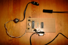
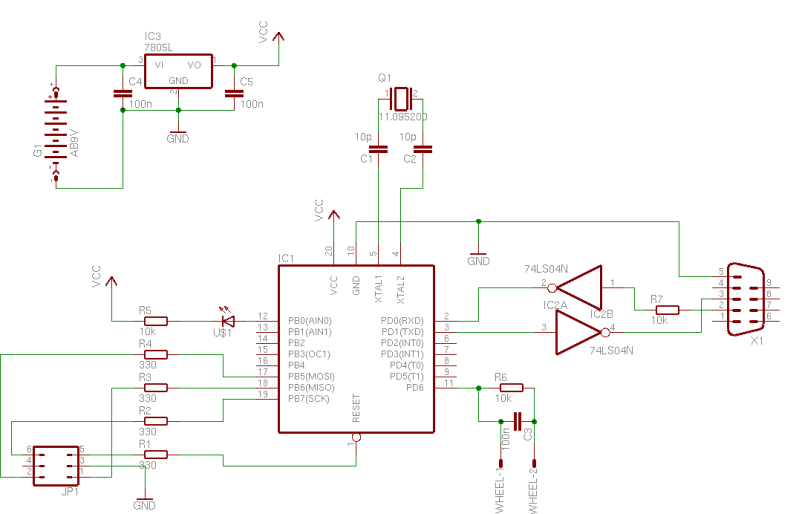
Here are the schematics. I have build the circuit on some test PCB for
my first drive.
; This source is for AT90S2313 controller running at 11.059 MHz
; I use PonyProg to program the controller
; all communication is done character based because of
; byte order incompatibility between Palm(motorola) and AVR(Atmel - Intel)
; Header includes to define various stuff.
.nolist
.include "2313def.inc"
.include "device.inc"
.include "regmap.inc"
.list
.org $0 ; at the start of memory the code just sets the
; interrupt vectors unused vectors are routed to
; the reset vector by putting their label at $0
.equ TLED =PB0
EXT_INT0:
EXT_INT1:
TIM_OVF0:
TIM_COMP1:
UART_DRE:
UART_TXC:
ANA_COMP:
rjmp RESET
rjmp EXT_INT0 ; IRQ0
rjmp EXT_INT1 ; IRQ1
rjmp TIM_CAPT1 ; Timer1 Capture
rjmp TIM_COMP1 ; Timer1 Compare
rjmp TIM_OVF1 ; Timer1 Overflow
rjmp TIM_OVF0 ; Timer0 Overflow, 5mS rate
rjmp UART_RXC ; UART Receive, serial data in
rjmp UART_DRE ; UART empty
rjmp UART_TXC ; UART Transmit
rjmp ANA_COMP ; Analog comparator
RESET: ; execution begins here after reset or cold start
; first we setup the stack
ldi TEMP,low(RAMEND) ; set the stack to the end
out SPL,TEMP ; of ram
; determine the baud rate generator value dependant
ldi TEMP, 5 ; 115200 at 11.059Mhz Maximum palm speed
out UBRR,TEMP
; setup the UART control register to enable receive interrupts
; and enable both the receive and transmit sides of the UART
ldi TEMP, (1<<RXCIE)+(1<<RXEN)+(1<<TXEN)
out UCR,TEMP
; setup the timer1
ldi TEMP,(1<<CS12)|(1<<CS10)|(1<<ICNC1); timer clock = system clock / 64
out TCCR1B,TEMP
ldi TEMP,1<<ICF1
out TIFR,TEMP ; Clear ICF1/clear pending interrupts
ldi TEMP,(1<<TICIE)|(1<<TOIE1)
out TIMSK,TEMP ; Timer/Counter1 Capture event interrupt
sbi DDRB,TLED
cbi PORTB,TLED
cbi DDRD,PD6 ; set PD6/ICP as input
sbi PORTD,PD6 ; enable PD6/ICP pull up
ldi TEMP,(1<<ACD) ; turn off the analog comparator
out ACSR,TEMP ; to minimize current draw
cbr STATUS,exp2(CAPTURE) ; first capture is valid
MAIN: ; clear the input stream counters and wait for data
ser CAPVALL ; initialize to maxspeed
ser CAPVALH ; initialize to maxspeed
clr WHEELR1 ;
clr WHEELR2 ;
clr WHEELR3 ;
clr WHEELR4 ;
; reset input variables
SCLEAR:
clr SERDAT ; and the position data
clr CHAR ; which character is being received
sei ; enable global interrupts and start interrupting!
CLEAR: ; get ready for the next bit of data to arrive
clr IDATA ; clear the last received data
MLOOP:
cpi IDATA,0 ; any data?
breq MLOOP ; nope, look until data is available
; out UDR,IDATA ; send the data back to the host
cpi IDATA,'r' ; Reset all values like wheelrounds and kmph
breq MAIN
cpi IDATA,'g' ; get all data
brne CLEAR
; rcall CRLF ; FOR DEBUGGING WITH PC
getkmph: ; 4 characters for speed
mov TEMP,CAPVALH
rcall hex2ascii
mov TEMP,CAPVALL
rcall hex2ascii
getwheelr: ; 8 characters for wheelrounds
mov TEMP,WHEELR4
rcall hex2ascii ; convert and send down the serial port
mov TEMP,WHEELR3
rcall hex2ascii
mov TEMP,WHEELR2
rcall hex2ascii
mov TEMP,WHEELR1
rcall hex2ascii
rjmp CLEAR ; gives a total of 12 characters send to the palm
; convert and display 2 hex digits in TEMP and sends it down the serial port;
hex2ascii:
push TEMP ; save for lower nybble
swap TEMP ; get upper nybble
andi TEMP,0x0f ; mask
cpi TEMP,0x0a ; is it 0-9?
brlo okhi ; yup
subi TEMP,-(7) ; else add 7 to make it a-f
okhi:
subi TEMP,-(0x30) ; make it ascii
rcall send
pop TEMP ; now do the lower nybble
andi TEMP,0x0f
cpi TEMP,0x0a
brlo oklo
subi TEMP,-(7)
oklo:
subi TEMP,-(0x30)
send:
out UDR,TEMP
txwait:
sbis USR,UDRE ; wait until transmit completed
rjmp txwait
ret
CRLF:
ldi TEMP,13
out UDR,TEMP
rjmp txwait
; if timer1 capture interrupt routine is to long (timing inaccuracy) we should use
; a flag to indicate the capture event occured and handle it from the main routine.
TIM_CAPT1:
push TEMP ; save temp
in TEMP,SREG ; get status register
push TEMP ; and save the status register
sbrc STATUS,CAPTURE ; check if this is a valid capture so no timer overflow occured
rjmp invcap
in CAPVALL,ICR1L ; we will deal with the full timer value
in CAPVALH,ICR1H ;
cbi PORTB,TLED ; Led for debugging and installation reasons
invcap: ; noop not a valid capture
cbr STATUS,exp2(CAPTURE) ; but it could get valid
clr TEMP ; reset the timer for the next measurement
out TCNT1H,TEMP
out TCNT1L,TEMP
inc WHEELR1 ; wahtever happened it is still a wheelround
brne donecap ; check for wheelr_low overflow
inc WHEELR2 ; then increase wheelr_high
brne donecap ; check for wheelr_low overflow
inc WHEELR3 ; then increase wheelr_high
brne donecap ; check for wheelr_low overflow
inc WHEELR4 ; then increase wheelr_high
donecap:
pop TEMP
out SREG,TEMP ; restore status
pop TEMP ; restore TEMP
reti ; exit interrupt
; the overflow interrup routine
TIM_OVF1:
push TEMP ; save temp
in TEMP,SREG ; get status register
push TEMP ; and save the status register
ser CAPVALL ; at overflow the speed is LOW
ser CAPVALH ; at overflow the speed is LOW
sbr STATUS,exp2(CAPTURE) ; the next capture is invalid
sbi PORTB,TLED ; Led for debugging and installation reasons
pop TEMP
out SREG,TEMP ; restore status
pop TEMP ; restore TEMP
reti ; exit interrupt
UART_RXC:
; Interrupts upon receipt of serial data.
in IDATA,UDR ; get the serial input data
; IDATA also flags the main rtn
; that data was received
; IDATA is cleared by the MAIN routine
reti